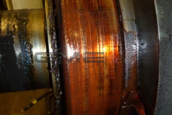
However, it is not only in our diagnostic reports that we attach great importance to accuracy. If a repair can be carried out on site, you can also expect a detailed and comprehensible report from us. Here, too, we attach great importance to the price transparency of our services.
Below you will find an exemplary on-site service report.

Make: A.v.K
Type: DSG 86 L1-8WNumber: 8127811 A103
Spg. Controller: Cosimat N+
Power: 1219 KVA – 1564 A – 900 rpm – 5500 kg

Upon arrival on board, the generator listed above had already been dismantled on the B-side (by the crew) in order to replace the defective exciter rotor winding.
The front winding head was sawn off and removed to push the individual coil legs backwards through the grooves, after which the grooves were cleaned and insulated for the new winding. The new winding was inserted, connected, phase-insulated, bonded and impregnated several times with special casting resin. Finally, the winding was tested with 1000 V DC against each other and to earth and found to be OK.
The connecting cables between the winding and the diode carrier run through an axial bore in the shaft; these cables were removed by the crew and replaced by us. Finally, the cables were checked against each other and against earth at 1000 V DC and found to be OK.
After the generator was completely reassembled, the first start was carried out without a voltage regulator (remanence voltage = 66 volts AC). The excitation was then specified with an external voltage source in order to carry out all open-circuit measurements; the measured values were compared with the test report and found to be OK. The next step was to commission and adjust the new voltage regulator. The generator showed normal operating behavior in single and parallel operation. Finally, the voltage regulators on all 3 generators were readjusted and a load run was carried out to full satisfaction.

Main pole winding I – K : 2.56 Ohm
Excitation stator I – K : 11.95 Ohm
Auxiliary winding UH1 – UH2 : 0.285 Ohm
Auxiliary winding WH1 – WH2 : 0.290 Ohm
All windings were tested with a test voltage of 500 V DC to earth.
Determined measured value: >550 MOhm
With star point connection
U – V : 0.336 Ohm
U – W : 0,337 Ohm
V-W : 0.339 Ohm
The winding was tested for phase closure and to earth with a test voltage of 1000 V DC.
Measured values determined:
Winding to phase closure : >550 MOhm
Winding to earth : >550 MOhm
Resistance of the standstill heating: 142 Ohm
Remanence voltage without excitation at the stator
With excitement
Stator voltage U – V – W : 452 V AC
Auxiliary voltage UH1 – UH2 : 85 V AC
Auxiliary voltage WH1 – WH2 : 86 V AC
Excitation stator I – K : 16.1 V DC
Excitation current I – K : 1.4 A DC
Stator voltage U – V – W : 447 V AC
Auxiliary voltage UH1 – UH2 : 87 V AC
Auxiliary voltage WH1 – WH2 : 87 V AC
Excitation stator I – K : 25.7 V DC
Excitation current I – K : 2.1 A DC